marcapra wrote:Wayne, I'm very impressed with your total dedication and inspiring work that you are doing on these neglected, until now, Victrola Electrola sets! Keep up the great work! Your friend, Marc.
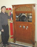
I had hoped that I would live out my days without buying, selling or even thinking about one of these. But clients of mine begged me to find them a restored 9-55. Thus, Wayne is "The Man" and on top of everything else, he is helping me deliver and set it up. What a guy!
Thanks Carlton, Marc, Russie, and Raphael for your kind sentiments.
Russie, I’m sorry but I can’t free up any spares until I finish my Electrolas. I have quite a few imcomplete machines that I’ll be needing parts for and I don’t know what needs replacing in the complete machines. As I previously mentioned, I’m not going to be installing any capacitors in series since they make single capacitors that can handle high voltages (1200V). I was already going to install a 1 amp fast blow fuse on the primary side of the power transformer. However, could you possibly tell me precisely where you put a fuse on the audio output circuitry and what value? I’ve included the schematic below.
PS It was pretty cool to watch the Fort Lauderdale Air Show from the pool today. Picture below of the Blue Angles making their version of the American flag over head.
Correction: Though the Blue Angels performed spectacularly, it was the Geico Skytypers using vintage WWII propeller planes.
Attachments
Last edited by Victrola-Monkey on Sun May 05, 2019 1:39 pm, edited 1 time in total.
Oops, sorry Wayne. I re-read your thread and indeed you are not installing series caps. My bad. I like your final choice of caps.
One good place to put a fuse is inline with the input power line, as you have mentioned already. The second good place is inline with the output tube. On your diagram, if you follow the filament of the #10 tube back to the filament winding, you'll see the windings are also in parallel with a rheostat. The center tap of that rheostat then goes to a 1400 ohm resistor, of which the other end is connected to ground. Insert a ¾ or 1 A fuse inline there, between the center tap of the rheostat and the resistor. That will protect both the tube and the transformer, both of which would be very expensive to replace if damaged by overload. Do not place a fuse inline with the plate (B+) circuit as the voltage there would exceed the rating of most fuses.
If you need a ballast tube, I have a few spare UV876.
Thanks Russie, I really appreciate the fuse tip and will incorporate it. I have added your interest for the amp/spkr to my list of members looking for Electrolas and their parts. I also made a note about the 876 that might be needed in the future.
startgroove wrote:
One good place to put a fuse is inline with the input power line, as you have mentioned already. The second good place is inline with the output tube. On your diagram, if you follow the filament of the #10 tube back to the filament winding, you'll see the windings are also in parallel with a rheostat. The center tap of that rheostat then goes to a 1400 ohm resistor, of which the other end is connected to ground. Insert a ¾ or 1 A fuse inline there, between the center tap of the rheostat and the resistor. That will protect both the tube and the transformer, both of which would be very expensive to replace if damaged by overload. Do not place a fuse inline with the plate (B+) circuit as the voltage there would exceed the rating of most fuses.
Cheers, Russie Ofria
Russie,
The connection between the 1400 ohm resistor and the control is the bias supply for the 10 tube, won't help much there. If you want protection from a shorted 81 or filter cap put the fuse in the center tap of the power transformer that's the sum of all the currents drawn from the supply. I wouldn't bother with a fuse in the AC side as the ballast tube will control the input current and if it is massive it will open.
Chuck,
You are correct in that the 1400 ohm resistor helps bias the #10 tube, by raising the cathode voltage a little more than chassis ground. Yet, it is also the main pathway for the DC flow through that tube. If that resistor opens, there would be no way for current to pass through the circuit properly, because the cathode would be floating, thereby effectively preventing the tube from conducting (assuming that all other components are good). A fuse in series with that resistor would pass the same current as the resistor, and if the current rating of the fuse is exceeded enough to blow the fuse, again the cathode would be floating. The filaments would still light, but overall bias would be completely outside the operating requirements of the tube. I avoid putting a fuse in the high voltage circuit in the interest of safety, since most fuses are rated at a maximum of 250V.
The fuse location I'm recommending was originally part of the design scheme for Operadio Amplifiers as used in the Mills Hi-Boy, Mills Troubadour and Seeburg Audiophone jukeboxes in the late Twenties. Their method was to use a fusible resistor as the cathode resistor. Their design was quite similar with these early RCA amplifiers, so it made sense to me to borrow that part of their design, but instead leave the existing cathode resistor and just add a fuse. I've tested it and it works well.
The protection I'm discussing here is based on the assumption that it would be the #10 tube that shorted, which could take out the output transformer, or the 81's. It would not protect against the output transformer itself from shorting, but if that happens no protection is going to save it anyway.
Cheers, Russie
I should add... the ballast tube only drops a fraction of the input voltage, I think around 30 volts at low load. If the power transformer were to short, the ballast tube would go way over voltage and could burn open. They are not that easy to find, so fusing the source voltage line is a good idea.
The resistor IS the bias setting device for the tube and it is actually much more than a few volts typically between 25 and 50 volts.
I see your point of the fuse in the cathode of the 10 protecting parts of the circuit from a catastrophic failure in the 10. But it will do nothing for a shorted 81, shorted filter cap or any failure before the output tube. The fuse in the return leg of the power transformer has no appreciable voltage referenced to ground but handles all the current from all the components. So with just that one fuse you are protected from a shorted 10, 81, filter cap, and output transformer.
Thank you so much Russie and Chuck for your discussion on where and why fuses should be added. I do realize this is to address hypothetical failures and provide valuable component protection plus safety considerations, so it is understood there’s multiple ways to address this with the addition of fuses to the original design.
So, if I could sum up the recommendations, Russie suggests the addition of F1 and F2, and Chuck suggests the addition of F3, as indicated on the schematic below. So it seems to me from your discussion, If F1 and F3 were added, that would cover all concerns brought up. Is this right? Or should I add all 3 fuses? That might be over doing it, but I’ll do what’s best, no need to worry about costs at this point.
The cap cans are stuffed (with wood and bees wax), sealed up, retested, and now going to prep to paint. The wire wound resistors are all set up for there proper values and ready to be wired up.
Wayne, If you go the F1/F3 route, it would be better to put F3 in line with the plate circuit, between the output transformer and the power transformer. That way, if there is a short in the output transformer to chassis ground, or anywhere in that circuit, or any overload for that matter, all DC power will be disconnected from the entire amplifier, after the fuse.
Keep in mind that the voltage along that circuit will be about 400 VDC above chassis ground, so isolate the fuse holder well and try to find a fuse that is rated higher than that.
All voltages that I give in this discussion are not absolute. Leaky transformer windings, or capacitors, or other components will vary it up or down. In addition, they are dependent upon the line voltage in a particular part of the country. For example, in my area it is 124 VAC.
Good to see you are opting for redundant safety measures!
![[The Talking Machine Forum - For All Antique Phonographs & Recordings]](/styles/we_universal/theme/images/the_talking_machine_forum.png)