![[The Talking Machine Forum - For All Antique Phonographs & Recordings]](/styles/we_universal/theme/images/the_talking_machine_forum.png)

I have been scratching my head for some time now trying to work out what motor would have been originally fitted to the EMG Mk X that I bought at auction last year. Initially I thought it would have been a Paillard GGR but the holes in the motor board just do not line up.
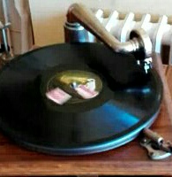
Currently fitted is an HMV 34 four spring motor together with turntable, brake and speed indicator/control which actually work very well.
Hopefully I have attached below a number of pictures but I make the following observations:
1) There are several holes in vicinity of brake showing something different was fitted in the past.
2) There are no additional holes in vicinity of speed control.
3) There are screw holes and larger penetration in top right corner of deck, (towards tone arm pivot).
4) Only other holes for motor attachment are 2 close to left side of spindle.
5) There is redundant winding hole approx 45mm to rear of spindle and approx 70mm below deck level.
6) Nickle plated horn tube is not on centreline but displaced to left by approx 25mm.
7) Motor board support rails only show the screw holes for present screws.
8) Centre of tone arm pivot to spindle is 11" and to needle point 11.5"
Any opinions or observations would be most welcome and if further pictures would assist I will try to post them.
Thanks for your help.
Iain
EMG Mk X Query
-
Inigo
- Victor VI
- Posts: 3777
- Joined: Mon Dec 18, 2017 1:51 am
- Personal Text: Keep'em well oiled
- Location: Madrid, Spain
- Contact:
Re: EMG Mk X Query
I'm near profane in these machines... but I would swear that the internal sound conduit was much longer, going all around three sides of the case, internally, around the motor, before entering the horn connection....! The one herein fitted seems like the short conduit of the HMV32... Or maybe this was in the more advanced Xa/Xb/Xb Oversize machines?
Inigo
-
emgcr
- Victor IV
- Posts: 1088
- Joined: Mon Jul 02, 2012 9:57 am
- Location: Hampshire, England.
- Contact:
Re: EMG Mk X Query
Inigo, without being able to measure it, the under deck-board conduit looks correct for the Mk X/Xa models and would be two inches shorter than the later Xb and Xb Oversize examples---see photo attached. The Mk X was expensively manufactured from cast bronze and plated with nickel on the vertical section appearing above the deck-board. The Xa, Xb and Xb Oversize models employed unplated cast aluminium.
- Attachments
-
- EMG X/Xa and Xb/Xb Oversize conduits contrasted.
-
IainW
- Victor O
- Posts: 72
- Joined: Sat Feb 06, 2021 2:29 pm
Re: EMG Mk X Query
Thanks Graham. Does the top of the nickel plated section screw off to allow the tube to pass through the deck board with minimal gap during construction?
Also any clues as to what the original motor might have been?
Iain
Also any clues as to what the original motor might have been?
Iain
-
emgcr
- Victor IV
- Posts: 1088
- Joined: Mon Jul 02, 2012 9:57 am
- Location: Hampshire, England.
- Contact:
Re: EMG Mk X Query
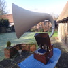
Iain, firstly many congratulations on having managed to buy the very rare Mk X EMG ! Are you lucky enough also to have the original horn and in good upright condition ? I am sure you know that most have collapsed due to poor design. Photos of the complete machine would be much appreciated.IainW wrote: ↑Mon Jan 31, 2022 5:10 am I have been scratching my head for some time now trying to work out what motor would have been originally fitted to the EMG Mk X that I bought at auction last year. Initially I thought it would have been a Paillard GGR but the holes in the motor board just do not line up.
Currently fitted is an HMV 34 four spring motor together with turntable, brake and speed indicator/control which actually work very well.
Hopefully I have attached below a number of pictures but I make the following observations:
1) There are several holes in vicinity of brake showing something different was fitted in the past.
2) There are no additional holes in vicinity of speed control.
3) There are screw holes and larger penetration in top right corner of deck, (towards tone arm pivot).
4) Only other holes for motor attachment are 2 close to left side of spindle.
5) There is redundant winding hole approx 45mm to rear of spindle and approx 70mm below deck level.
6) Nickle plated horn tube is not on centreline but displaced to left by approx 25mm.
7) Motor board support rails only show the screw holes for present screws.
8) Centre of tone arm pivot to spindle is 11" and to needle point 11.5"
Any opinions or observations would be most welcome and if further pictures would assist I will try to post them.
Thanks for your help.
Iain
You pose some interesting questions. Like you, my first thoughts regarding motors would be of Paillard GGR255 (similar to one I used to own) but, as you say, the hole fixings are different. I have looked at various other motors known to have been used by EMG but cannot find anything to match. As far as I can tell, it did not have Garrard, Collaro, Paillard or Cowey. I do not have a Thorens to check, apart from a really massive example which would not have fitted in the EMG case ! I can find no motor with two fixing holes to the left of the splndle. In any case, there surely must have been fixings on the right too, so again---complete mystery.
Your comment about the sideways-displaced conduit position is very intriguing indeed. This, in my opinion, points to a very early construction date and I have only seen one other---see attached photo. In this case the transposition was about 1 ½ inches. It is also fascinating to comment that this example, although with electrically operated Garrard 201 by the time of my ownership, had a redundant winder hole and escutcheon like yours and in much the same position as far as I can judge from photos. It defied all my attempts to establish the original motor, so the mystery remains ! If you look at the plate at the beginning of the Wilson/Webb book you will see the offset conduit position in even more pronounced form.
- Attachments
-
-
emgcr
- Victor IV
- Posts: 1088
- Joined: Mon Jul 02, 2012 9:57 am
- Location: Hampshire, England.
- Contact:
Re: EMG Mk X Query
The conduit itself is made in one casting and is secured by a threaded top ring with another underneath to promote stability. When dismantling, first unscrew the tonearm housing (three wood screws) and remove the whole assembly complete with tonearm (anti-clock) but try not to disturb the loose ball bearing setting (later models had a ball race which is much easier). Next, unscrew the top ring directly under the horn (anti-clock) having first removed the four wood screws (I made a special tool for this with variable peg drive--if you don't have one, careful use of an appropriate aluminium drift and hammer will suffice but do not slip !) and the conduit will then drop sufficiently to allow extraction from the case. The front deck-board with motor must first be removed together with the rear deck-board screws to allow horizontal sliding of the latter. The conduit can then be threaded out of the woodwork having first removed the four woodscrews securing the blanking plate around the position where the conduit emerges from the rear deck-board.
-
Inigo
- Victor VI
- Posts: 3777
- Joined: Mon Dec 18, 2017 1:51 am
- Personal Text: Keep'em well oiled
- Location: Madrid, Spain
- Contact:
Re: EMG Mk X Query
How interesting... Then maybe was Expert who used a conduit as I described? I've seen it in phantom view in an advert, but I don't remember where... Sure that it has been posted anywhere herein,.. but a search for 'expert' produces 130 pages of results!!!
Inigo
-
emgcr
- Victor IV
- Posts: 1088
- Joined: Mon Jul 02, 2012 9:57 am
- Location: Hampshire, England.
- Contact:
Re: EMG Mk X Query
These two photos show the internal conduit for the Expert Senior and Junior. The toneam emerges from the front of the deck-board in the case of the Senior (the longest), midway for the Junior and towards the back in the case of the Minor (shortest). Unlike EMG, Expert conduits were made in two parts which screwed together---internal and external---and in varying diameters. Interestingly, the threads joining the conduit to the tonearm bearing housing also fitted EMG.
- Attachments
-
- Expert Senior
-
- Expert Junior
-
IainW
- Victor O
- Posts: 72
- Joined: Sat Feb 06, 2021 2:29 pm
Re: EMG Mk X Query
Regret I do not have the Mk X horn. The horn it came with is a Xb (but it does sound magnificent). At the moment I have no plans to disassemble the conduit - there is more than enough machinery sitting in pieces around the garage awaiting my attention! Interestingly there is no blanking plate where the conduit penetrates the deck board, see photo below. Also the tonearm bearing plate has a small notch cut out of it to clear the adjacent deck board screw.
The case is exactly 18.5" wide, is this narrower than later models and the reason for the offset of the horn support?
I am guessing the motor board may be original as the only holes in the support rails are those currently in use.
The case is exactly 18.5" wide, is this narrower than later models and the reason for the offset of the horn support?
I am guessing the motor board may be original as the only holes in the support rails are those currently in use.
- Attachments
-
-
-
-
soundgen
- Victor VI
- Posts: 3001
- Joined: Mon May 13, 2013 2:04 pm
- Contact:
Re: EMG Mk X Query
Original motor Collaro D30 looking at the position of the holes on the motor board
- Attachments
-
- Bare Deck 1.jpg (54.17 KiB) Viewed 972 times
-