![[The Talking Machine Forum - For All Antique Phonographs & Recordings]](/styles/we_universal/theme/images/the_talking_machine_forum.png)

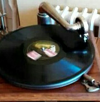
Many collectors like to play their older Victor/HMV machines. Unfortunately the poor tracking alignment causes rapid record wear as well as sound distortion so sadly it has always limited me to just playing junk records on these fine old machines.
I have made a tracking adaptor that considerably improves the tracking error and offset. It is made from brass (and would probably look better nickel-plated) with the various parts hard-soldered together. The brass is thinned to keep the weight down. It is made for use on the tonearm of my HMV No. 7 Monarch Senior but this is a standard tonearm common to many other Victor/Gramo Co. machines (early version pre slip-in elbow) not just other 12 inch turntable Monarch Seniors and the Victor V and VI but it was also used on many 10 inch turntable machines where a longer bracket was used to compensate for the difference in case size and the tonearm remains the same size. My hope is that the adaptor can be swapped around with similar tracking benefit.
My first attempt at making a tracking adaptor had the soundbox fitting protruding directly from the mouth of the tonearm. Unfortunately in tilting the soundbox forward into the correct alignment, this creates too much overlap (the distance the needle goes past the centre of the spindle). This was also the problem with my angled cork flange (isolator) to replace the one on the back of the soundbox, although I believe the benefit still outweighs the extra overlap. This latest adaptor not only tilts the soundbox into the correct alignment but it also pushes the soundbox back to achieve something very close to best overlap.
Tonearm length from pivot point to centre of the spindle is 10 5/16 inches (262mm)
BELOW IS LISTED MY BEFORE AND AFTER COMPARISONS:
OFFSET: Before 0, After 3 inches (75mm).
TRACKING ERROR on a 12 inch record:
Before; Start 19°, Middle 17°, End 14°.
After ; Start 3°, Middle 0°, End 1°.
OVERLAP: Before 9mm. After 9mm.
NOTE ON OFFSET: Offset shown is 'distance offset' also known as 'linear offset'. Offset can also be shown as 'offset angle' which, with the adaptor, is 16°. Using trigonometry this angle is useful in calculating exact distance offset. Using a piece of rubber tube (so called 'lifebelt') with a male soundbox adaptor I was able to extend offset from the adaptor to the ideal offset of 3 ¾ inches (95mm) or 20.5°. This maintained good alignment and rapidly increased overlap but this was inline with the extra overlap shown for extra offset. However, I could not find much significant benefit in tracking alignment and was relieved not to have made an adaptor which would give ideal offset because this would look too intrusive to the machine. As others have done, i'm sure, I also increased offset from the tonearm without the adaptor. To get any significant benefit the tube has to be too long and becomes unmanageable, takes up too much room and looks strange. Even at full offset it does not give the good alignment of the adaptor.
NOTE ON TRACKING: I made the adaptor have a beneficial bias to the later part of a 12 inch record. This is because it takes into consideration that 10 inch records will also be played (the tracking error at the start of a 10 inch record is 1.5° with adaptor) and that generally more sound is packed into a smaller area as the record progresses.
NOTE ON OVERLAP (also known as Overhang): Many thanks indeed to 'emgcr' for uploading the EMG booklet to this forum (link below) showing the table of best overlaps as well as other useful information. Nowhere else on the net have I been able to find such a table although Mr Reiss shows a similar table in his excellent book. Both tables give measurements in different units of an inch. For ease of comparison and to work with I have converted the 2 tables into millimetres and calculated the ratio for the exact length of tonearm and offset I have here. I calculate that overlap should be a just over 8mm although the tables do not quite agree with each other.
Here I would like to say that making this adaptor was easy to encourage others to have a go! But it wasn't. The adaptor not only has to give you the correct tracking angle but also maintain the 90° upright position of the soundbox (this was nearly as much of a problem as angle itself) and it has to give you the 60° angle (or your preferred angle) of the stylus bar, and acceptable overlap, oh, and it also has to be airtight! The first attempt gave too much overlap. The second attempt was great until it melted as I was trying to fill pits in the silver solder. This last attempt relies on much less solder so that melting wasn't likely to be such a problem. The pieces have to be fixed to more of less where you want them with a tiny amount of solder and then tested, reheated to be moved slightly, tested, reheated... maybe metal has to be added, taken away etc.
So I have come up with another way of making an adaptor. Here the brass collar (for tonearm fixing) is glued into a piece of cork (painted black, see picture) at approximately the right angle with glue. This is then screwed or bolted onto a brass plate that contains the fitting for the soundbox. The cork can be unscrewed and the underside sanded with a bias to one side or the other until the desired tracking alignment is achieved. The 90° upright position can also be achieved in this way. You can always add a layer of cork or filler if too much material is removed by mistake. You can also fill and change the position of the fixing holes to change overlap. Brass parts like the plate can be thinned down as much as you dare to keep the weight down. The problem with this adaptor is that it doesn't look as nice and discreet as the all-brass version although it achieves the same beneficial geometry. There are other ways of making it that I can think of but none as tidy and discreet as the permanent all-brass version. I would love to hear from anyone who has any ideas. I am not sure if the brass adaptor could be mechanically copied.
Jamie
Links:
http://forum.talkingmachine.info/viewto ... 11&t=15253
http://www.graham-ophones.co.uk/keeping ... 4590882209
The Compleat Talking Machine by Eric L Reiss (1986) Pages 99-102
Tracking Alignment Adaptor for the Exhibition Soundbox
-
jamiegramo

- Victor III
- Posts: 640
- Joined: Tue Sep 21, 2010 5:52 am
- Location: St. Albans, UK
Tracking Alignment Adaptor for the Exhibition Soundbox
- Attachments
-
-
-
- adapt3.JPG (60.28 KiB) Viewed 3092 times
-
Last edited by jamiegramo on Sat Aug 31, 2019 11:13 am, edited 1 time in total.
-
Roaring20s

- Victor V
- Posts: 2567
- Joined: Wed Jun 13, 2012 1:55 am
- Personal Text: Those who were seen dancing were thought insane by those who could not hear the music. Nietzsche
- Location: Tucson, AZ
Re: Tracking Alignment Adaptor for the Exhibition Soundbox
Not an easy task, nice work!
The following question is not about crafting of the adapter. But, your efforts have made me think about the needle and its improved fit in the groove. Since the modification to the reproducer's angles, how has the the wear pattern to the needle changed? Does it have less flattened wear to the leading edge? And, has the wear to the trailing edge of the needle increased?
It may not mean anything ... just thinking aloud.
James.
-
De Soto Frank

- Victor V
- Posts: 2687
- Joined: Wed Dec 01, 2010 1:27 pm
- Location: Northeast Pennsylvania
Re: Tracking Alignment Adaptor for the Exhibition Soundbox
Jamie -
Wow ! Quite an effort, and nice handy-work !
Have you noticed any reduction in "black dust" on the needles after a play ?
Frank McMullen
Wow ! Quite an effort, and nice handy-work !
Have you noticed any reduction in "black dust" on the needles after a play ?
Frank McMullen
De Soto Frank
-
jamiegramo
- Victor III
- Posts: 640
- Joined: Tue Sep 21, 2010 5:52 am
- Location: St. Albans, UK
Re: Tracking Alignment Adaptor for the Exhibition Soundbox
Thanks James and Frank for your nice comments!
I shall have to find my eye-glass to see the pattern of wear to the needle tip but I would expect it to be similar to one played on an orthophonic machine. Certainly there is far less black dust after a play. The needle simply does not wear as quickly causing the extra record wear and distortion as it travels through the record. There is none of the distortion normally associated with playing electrically recorded records on older poorly tracking machines such as this Monarch.
I shall have to find my eye-glass to see the pattern of wear to the needle tip but I would expect it to be similar to one played on an orthophonic machine. Certainly there is far less black dust after a play. The needle simply does not wear as quickly causing the extra record wear and distortion as it travels through the record. There is none of the distortion normally associated with playing electrically recorded records on older poorly tracking machines such as this Monarch.
-
Inigo
- Victor VI
- Posts: 3777
- Joined: Mon Dec 18, 2017 1:51 am
- Personal Text: Keep'em well oiled
- Location: Madrid, Spain
- Contact:
Re: Tracking Alignment Adaptor for the Exhibition Soundbox
You're a real Master! Very nice adaptor. The all-brass one certainly looks much better!
I was lately planning to form one adaptor from standard copper elbow fittings of adequate diameter. There's an elbow which is 45 degrees. My plans, still not made, were to cut one of these elbows at a minor adequate angle, by trial and error, to see if I could get the best tracking. I've also got fine cork jug caps to see if I could make a wedged back joint as you told us in a previous post.
Another plan was to get a spare gooseneck and cut out a section in the middle and rejoint it so it goes a different angle, less than the original 180 degrees. This would reposition the soundbox at an offset angle with the tonearm axis, and would reposition the soundbox farther from the tonearm, enlarging the distance between the pivot and the needle.
Inigo
-
jamiegramo
- Victor III
- Posts: 640
- Joined: Tue Sep 21, 2010 5:52 am
- Location: St. Albans, UK
Re: Tracking Alignment Adaptor for the Exhibition Soundbox
Hi Inigo, good to hear from you! I know you have an interest in this subject. No i'm not so much a master but a persistant idiot (or 'anorak').Inigo wrote:You're a real Master! Very nice adaptor. The all-brass one certainly looks much better!
I was lately planning to form one adaptor from standard copper elbow fittings of adequate diameter. There's an elbow which is 45 degrees. My plans, still not made, were to cut one of these elbows at a minor adequate angle, by trial and error, to see if I could get the best tracking. I've also got fine cork jug caps to see if I could make a wedged back joint as you told us in a previous post.
Another plan was to get a spare gooseneck and cut out a section in the middle and rejoint it so it goes a different angle, less than the original 180 degrees. This would reposition the soundbox at an offset angle with the tonearm axis, and would reposition the soundbox farther from the tonearm, enlarging the distance between the pivot and the needle.
I hope you do give it ago. Copper elbows and old tonearm parts are worth looking at as long as you can find something that fits well over the tonearm and something that then fits inside the soundbox. Plumbing parts can present some interesting possibilities. On certain shower heads there is an adjustable 'ball' joint. If this allows water through why not sound? An adaptor made with a ball joint could be easily set simply by tightening in the right tracking alignment on one machine and then moved to another machine and if need be re-adjusted and tightened again. I havn't had a chance to look at some of these fittings to see how feasible this idea really is but I suspect it might come down to actually making a ball joint.
Jamie
-
Inigo
- Victor VI
- Posts: 3777
- Joined: Mon Dec 18, 2017 1:51 am
- Personal Text: Keep'em well oiled
- Location: Madrid, Spain
- Contact:
Re: Tracking Alignment Adaptor for the Exhibition Soundbox
Very interesting the use of ball joints !
About copper, I actually found one copper elbow that fitted on the HMV101 tonearm and the other end "as is" fitted on the soundbox. I used it to make a Pathé adaptor for playing vertical records on the 101. I had to cut out part of the elbow, and make the L indent for the soundbox pin. But it worked.
I will try them on the HMV model 3 to see if it fits on the exhibition soundbox.
I've been thinking also of PVC plumbing connections, pipes and elbows. I must investigate in a plumbing store to see if something fits. I can carry the gooseneck with me and test the PVC parts I see...
Inigo
-
emgcr
- Victor IV
- Posts: 1088
- Joined: Mon Jul 02, 2012 9:57 am
- Location: Hampshire, England.
- Contact:
Re: Tracking Alignment Adaptor for the Exhibition Soundbox
Superb work Jamie---and much needed really to preserve our precious discs.jamiegramo wrote:
There are other ways of making it that I can think of but none as tidy and discreet as the permanent all-brass version. I would love to hear from anyone who has any ideas. I am not sure if the brass adaptor could be mechanically copied.
I have used 3D printing successfully to copy gramophone parts which could be appropriate here ? If you print in resin (metal is probably going to be prohibitive cost-wise) you could then copper plate to perhaps a wall thickness of 0.005" to give mechanical strength (be sure to allow for tolerances). Copper is extremely strong and has good ductility--nickel plating can then follow easily. In order to plate on the resin you would need to employ colloidal silver which is painted on to give an electrically conductive base. My local plating company here in the UK has carried this out successfully.
Here are photos of a Pathé Concert horn/tonearm "onion" joint manufactured in such a way.
- Attachments
-
-
-
-
- 3D printed onion after silver and copper but before final nickel (3).JPG (110.76 KiB) Viewed 2867 times
-
-
jamiegramo
- Victor III
- Posts: 640
- Joined: Tue Sep 21, 2010 5:52 am
- Location: St. Albans, UK
Re: Tracking Alignment Adaptor for the Exhibition Soundbox
Good to hear from you! Even though your overlap tables gave me problems! I did wonder about 3D printing but I've no experience of it and hoped someone would. It could be ideal even if just finished black to match the back of the soundbox. The only part that needs to be really strong is the locating screw which is added. Metal casting is out of the question, of course, because of shrinkage and I did wonder about plastic casting but perhaps 3D printing is more precise. Did someone do this for you? I can see how the copper would add strength.emgcr wrote:I have used 3D printing successfully to copy gramophone parts which could be appropriate here ? If you print in resin (metal is probably going to be prohibitive cost-wise) you could then copper plate to perhaps a wall thickness of 0.005" to give mechanical strength (be sure to allow for tolerances). Copper is extremely strong and has good ductility--nickel plating can then follow easily. In order to plate on the resin you would need to employ colloidal silver which is painted on to give an electrically conductive base. My local plating company here in the UK has carried this out successfully.
Here are photos of a Pathé Concert horn/tonearm "onion" joint manufactured in such a way.
The Pathé 'onion' looks great. On my little Pathé this part is pot metal which had expanded so that the elbow would no longer fit. Was this also pot metal that you replaced on this larger bracket?
-
Orchorsol

- Victor IV
- Posts: 1624
- Joined: Wed Feb 22, 2012 9:03 am
- Location: Dover, UK
- Contact:
Re: Tracking Alignment Adaptor for the Exhibition Soundbox
That's a really great piece of work Jamie, thanks for posting. As well as alleviating record wear it's interesting to hear that later records actually sound better too.
It's exciting to think you could possibly make some of these along the lines that Graham has suggested - perhaps if the resin/copper won't quite support the screw with enough strength, you could bond a threaded insert in? If you do end up producing a number of these in future, I may well be in line for one for my baby monarch!
It's exciting to think you could possibly make some of these along the lines that Graham has suggested - perhaps if the resin/copper won't quite support the screw with enough strength, you could bond a threaded insert in? If you do end up producing a number of these in future, I may well be in line for one for my baby monarch!
BCN thorn needles made to the original 1920s specifications: http://www.burmesecolourneedles.com
Youtube channel: https://www.youtube.com/channel/UCe4DNb ... TPE-zTAJGg?
Youtube channel: https://www.youtube.com/channel/UCe4DNb ... TPE-zTAJGg?