![[The Talking Machine Forum - For All Antique Phonographs & Recordings]](/styles/we_universal/theme/images/the_talking_machine_forum.png)

Hi -
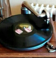
I am trying to repair a Victrola IX. It was made around 1914, and has a crescent-shaped speed indicator dial as shown.
The governor had been messed with and one spring was replaced with a wire. So I replaced all three governor springs, but the machine is running too slowly. I compared the governor to other Victrola IX machines, as well as a governor from a parts machine as shown in the photo, and I notice a difference. The central brass tube that slides on the shaft on the right is shorter than the others. Is there something wrong with the governor that I am rebuilding (on the left in the photo), or is this just another style of governor with a shorter tube that was being used with the speed indicator shown? (I am sure that am am not using the correct nomenclature here).
Victrola Governor Issues
-
MikeB

- Victor II
- Posts: 398
- Joined: Mon Aug 30, 2010 9:28 am
Victrola Governor Issues
- Attachments
-
-
- file.jpg (152.4 KiB) Viewed 882 times
-
Inigo
- Victor VI
- Posts: 3776
- Joined: Mon Dec 18, 2017 1:51 am
- Personal Text: Keep'em well oiled
- Location: Madrid, Spain
- Contact:
Re: Victrola Governor Issues
The shorter tube may be a later style. It doesn't mind at all, it only allows the governor to get more expanded when working, i.e. greater speed range... No problem provided that at full speed, the balls don't hit anything (the motor frame, etc).
Your machine goes too slow because you have to adjust slightly the governor bearings. They are fixed in position with set screws. With the motor completely run down, you may unscrew them a few, then slide the governor slightly back towards the round brass plate (let's call back the plate side, and front the worm side) , then fix the back bearing firmly with the screw, then adjust the front bearing, letting the governor a minuscule gap so it can move a little back and forth in its bearings, then fix the front screw. Wind and test again watching that you can reach speeds lower than 78 and higher too, with 78 in the middle, and making sure the balls don't hit anything at the maximum speed.
You'll have to adjust the speed lever too, so 78 will fall in the middle of its range. It has a set screw too, allowing the speed lever to be shifted without moving actually the speed, until you set the right position, then fix its screw.
Inigo
-
Jerry B.
- Victor Monarch Special
- Posts: 8514
- Joined: Tue Feb 10, 2009 11:25 am
- Personal Text: Stop for a visit when in Oregon.
- Location: Albany, Oregon
Re: Victrola Governor Issues
If you follow the metal bar that contacts the underside of the speed control to the motor and governor, there is generally an adjustment point that can be used to make the correction you wish. If there is nothing you can adjust the governor but I use that as a last resort.
Jerry Blais
Jerry Blais
-
MarkELynch
- Victor II
- Posts: 325
- Joined: Tue Jun 02, 2009 10:19 pm
- Location: Silver Spring, MD
Re: Victrola Governor Issues
Hi Mike,
While it is important to be sure the governor spins freely on its two bearings with minimal end play the Victrola governor bearing next to the spindle is designed to be placed in only one position. The bearing nearest the spindle has a Vee groove to engage the bearing set screw, it should go in one position only. The end play adjustment is made with the opposite bearing which has no Vee groove.
Be sure that the small ball (thrust) bearings are contained in each of the governor bearing bores.
Try repositioning the arm that holds the governor friction leather. Loosen the square headed set screw in the arm and rotate it on the regulation shaft and retighten. Repeat until you correct the speed. Before doing this set the knurled bolt on speed adjustment up top in the middle of its range so you can fine tune the speed from above.
Regarding the governor, the governor shaft has a spot drilled to accept the set screw in the spring collar. This is the small collar, not the larger collar containing the brake disc. Check this before making the above adjustment.
Let us know how things turn out.
Mark
-
Inigo
- Victor VI
- Posts: 3776
- Joined: Mon Dec 18, 2017 1:51 am
- Personal Text: Keep'em well oiled
- Location: Madrid, Spain
- Contact:
Re: Victrola Governor Issues
Under the light of my humble experience, and some surprises found when repairing old hmv motors (which might well be of Victor make, or might be the european variants of those) I would like to add some notes to Mark's instructions :
The back brass bearing (the one near the spindle, the thrust bearing) may or may not have the V groove for a fixed position; at least in old style hmv motors it might not be present, so the governor position must be found by trial and error.
The governor axis may or may not have the dimple for the fixed position of the small governor collar set screw. Same reasons as above.
I don't know if Victor motors always had these features for exact adjusting. Earlier hmv motors didn't until a certain era. So in those, you had to try all four fine governor adjustments: the governor collar position on its axis, the governor axis and bearings positions on the motor frame, the square head set screw for the brake lever end portion, the speed lever hand adjustable position... Too many things!
You should check and examine first your original bearings and governor axis. Sometimes, the swapping of an original governor by a more modern one with pre-set positions may require to jump over those pre-set features, and may require adjustments out of these pre-set positions to be reusable on an older motor...
Inigo
-
MikeB
- Victor II
- Posts: 398
- Joined: Mon Aug 30, 2010 9:28 am
Re: Victrola Governor Issues
Thanks very much. I had pretty much came to the conclusion that I need to adjust the end of the speed control arm with the square-headed screw when I read Mark's post, so thanks for verifying that. I can get the machine to play at the right speed, but the top of the speed adjustment arm is in totally the wrong place when I do that. The square-headed screw is pretty frozen, though, and I am worried about breaking it. So I need to figure out how to get the adjustment arm out of there and carefully work on it...MarkELynch wrote: ↑Tue Jun 08, 2021 11:47 am Hi Mike,
While it is important to be sure the governor spins freely on its two bearings with minimal end play the Victrola governor bearing next to the spindle is designed to be placed in only one position. The bearing nearest the spindle has a Vee groove to engage the bearing set screw, it should go in one position only. The end play adjustment is made with the opposite bearing which has no Vee groove.
Be sure that the small ball (thrust) bearings are contained in each of the governor bearing bores.
Try repositioning the arm that holds the governor friction leather. Loosen the square headed set screw in the arm and rotate it on the regulation shaft and retighten. Repeat until you correct the speed. Before doing this set the knurled bolt on speed adjustment up top in the middle of its range so you can fine tune the speed from above.
Regarding the governor, the governor shaft has a spot drilled to accept the set screw in the spring collar. This is the small collar, not the larger collar containing the brake disc. Check this before making the above adjustment.
Let us know how things turn out.
Mark
Thanks again.