![[The Talking Machine Forum - For All Antique Phonographs & Recordings]](/styles/we_universal/theme/images/the_talking_machine_forum.png)

I'm looking for a wiring diagram for my electric induction motor VE-230. The motor runs well plugged into an outlet but when plugged into the machines wiring it doesn't work (the light lights up fine though).
It seems there is 6 wires coming in. 2 go to the upper right of the horn (which powers the light), 2 go the other left, then 2 go behind the horn where one wire branches off to the plug (where the motor gets plugged in).
Seems little over confusing to me but I would like to rewire it to make it safer.
VE victrola wiring diagram
-
travisgreyfox

- Victor IV
- Posts: 1156
- Joined: Sat Aug 12, 2017 9:25 pm
VE victrola wiring diagram
- Attachments
-
-
-
-
VanEpsFan1914
- Victor VI
- Posts: 3178
- Joined: Fri Oct 06, 2017 11:39 am
- Personal Text: I've got both kinds of music--classical & rag-time.
- Location: South Carolina
Re: VE victrola wiring diagram
The first thing you need to do is trace out the original wiring as it is in there. With everyone in a hurry to re-wire, the original lengths, colors, and gauges of wire are going to be easy to forget. You can find appropriate wire from Sundial Wire or the Vintage Wire & Supply Company. I think this one would have a cotton-covered cord, though rayon is also going to give a good period appearance (mimicking wires covered in silk.)
A VE-230 is really only going to have a couple of pieces on the circuit:
a line plug (to the wall)
a motor
a light bulb
a power switch
It's going to be very easy to figure out what the original wiring harness looks like in there.
A VE-230 is really only going to have a couple of pieces on the circuit:
a line plug (to the wall)
a motor
a light bulb
a power switch
It's going to be very easy to figure out what the original wiring harness looks like in there.
-
MarkELynch
- Victor II
- Posts: 326
- Joined: Tue Jun 02, 2009 10:19 pm
- Location: Silver Spring, MD
Re: VE victrola wiring diagram
Travis,
Here is information from Victor Service Bulletin No. 17 regarding the induction disc motor. Is there a full wiring diagram on a paper label pasted to the machine? This label was typical on the larger Electrolas. I don’t have a VE-230 in the collection to check. For the light, put the lid support switch in series with the hot side of the line. The pictured resistor may not be present in your machine.
Good luck.
Mark
-
MarkELynch
- Victor II
- Posts: 326
- Joined: Tue Jun 02, 2009 10:19 pm
- Location: Silver Spring, MD
Re: VE victrola wiring diagram
Travis,
Would you like to share your progress with us?
Mark
Would you like to share your progress with us?
Mark
-
travisgreyfox
- Victor IV
- Posts: 1156
- Joined: Sat Aug 12, 2017 9:25 pm
Re: VE victrola wiring diagram
Yeah, thanks for the information Charles and Mark. I still haven't dug deep into anything yet, but depending on how the wires are sitting the light will work and the motor isn't getting power or if I move the wires a bit the motor will turn on and run great but the light wont power on. It just needs new wires throughout.MarkELynch wrote: ↑Wed Aug 31, 2022 3:29 pm Travis,
Would you like to share your progress with us?
Mark
Mine doesn't have the diagram on it, so thank you for the that piece of information about the lid switch wire Mark. I have slowly been working on getting the outside of the machine looking decent while I was waiting for more funds to pour into it. I luckily just sold a portable record player on eBay so now I can start doing real work on it.
Quick question: If this machine was yours would you remove the entire horn before starting the wire job or just work around it? I've taken a horn out before and it was a pain putting it back in then trying to reseal it.
Thanks,
Travis
-
travisgreyfox
- Victor IV
- Posts: 1156
- Joined: Sat Aug 12, 2017 9:25 pm
Re: VE victrola wiring diagram
I just kind of tightened everything up and now the motor spins good and the light works as it supposed to. I'll probably still re-wire everything eventually to make it safer, but it's good right now (I keep it unplugged when not in use).
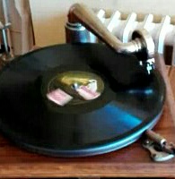
It came with the light cover thing off and I cant find a pic of one online. Can somebody explain how the little gold "shade" goes on properly. Maybe I'm missing some pieces?
It came with the light cover thing off and I cant find a pic of one online. Can somebody explain how the little gold "shade" goes on properly. Maybe I'm missing some pieces?
- Attachments
-
-
-
MarkELynch
- Victor II
- Posts: 326
- Joined: Tue Jun 02, 2009 10:19 pm
- Location: Silver Spring, MD
Re: VE victrola wiring diagram
Hi Travis,
I’m glad you are making progress!
The gold light shade is one piece but yours is deformed. The two tabs on the small end of the shade are designed to simply clip around the top of the light bulb socket. Have a go at straightening your shade and it should clip right on.
If you are unsuccessful I have a spare shade that I can send you. This was a common part on several Electrola models and is often missing so you are fortunate to have it. Many owners of the early Victor 10-50 Automatic machines from 1927 would love to find their missing shade. The position of the bulb on later production 10-50’s was moved to the ceiling of the changer compartment and it no longer required a shade to eliminate the glare.
Mark
-
Inigo
- Victor VI
- Posts: 3777
- Joined: Mon Dec 18, 2017 1:51 am
- Personal Text: Keep'em well oiled
- Location: Madrid, Spain
- Contact:
Re: VE victrola wiring diagram
I'm not in this .. but a photo of your correct shape shade would help our colleague... 
Inigo
-
travisgreyfox
- Victor IV
- Posts: 1156
- Joined: Sat Aug 12, 2017 9:25 pm
Re: VE victrola wiring diagram
Thanks again Mark. I'm thinking the bent part is above the "heart" shaped hole in the shade? As Inigo suggests a pic would be great to not only see what it looks like unmolested on a machine, but to give me a chance to see what a "correct" looking bulb from the time period looks like (if anybody has this setup).
Thanks
Travis
Thanks
Travis
-
MarkELynch
- Victor II
- Posts: 326
- Joined: Tue Jun 02, 2009 10:19 pm
- Location: Silver Spring, MD
Re: VE victrola wiring diagram
Here is the photo you requested. The original bulb is a 2” diameter frosted globe with a tip at the top where the air was exhausted when the bulb was manufactured. Notice the small cut-out at the top of the shade to accommodate the tip. Since the tip was eliminated years ago a modern frosted bulb with a candelabra base like the one in my photo is a reasonable substitute. Antique bulbs with the tip can be had at a price.
Mark
.
Mark
.