![[The Talking Machine Forum - For All Antique Phonographs & Recordings]](/styles/we_universal/theme/images/the_talking_machine_forum.png)


http://s13.invisionfree.com/OTVMMB/ar/t192.htm
The text is below:
View Full Version: Help with Universal Motor on HMV
Old Time Victrola Music Message Board > Antique Phonograph Message Board > Help with Universal Motor on HMV
Title: Help with Universal Motor on HMV
Description: Automatic 1 HMV motor
Moooperator - February 21, 2009 10:53 PM (GMT)
Gents,
I now have the 1A back together and I am afraid to turn it on!
I've checked the voltage to all parts of the machine. US voltage is 110 and I have 120v going through the converters (which should be in range) and to the 3 areas that current goes to all are reading 120v. To the light, the remote and the motor.
Now, I was told the voltage to the motor should be 32v... is that right? the plug that goes to it reads 120. I turned it on and it is running smoothly but i only left it on about 30 sec. I don't want to burn it up. When I got it originally, one of the brushes was making it arch and I had that repaired.
Am I ready to start playing records or is there something I need to adjust in the converters to the motor to get 32 v? I though the manual said it needed at least 65v to run. When I got it is was still set to UK 240v in the converters.
Any help would be greatly apprecaited... can't wait to get it running and compare it to the Victrola 10-50.
Regards
Jeff aka Mooo :woof:
wjw - February 22, 2009 12:45 AM (GMT)
Moo, what voltage do you have to the motor?
[Marjorie Main] - February 22, 2009 02:44 AM (GMT)
Greetings, oh Bovine One!
As W says, check to see the actual voltage that is going to the motor and also check to see if the motor itself doesn't have a resistor coil on it somewhere. If the speed is correct at the turntable, you *probably* have it correct.
There are two ways to do it. If the motor is universal (which means they've put a full wave bridge rectifier in there or the motor is internally bridged) you only need to worry about the DC characteristics of the actual motor.
The difficult way (don't worry about this because its a PITA to do if you don't have a piece of equipment called a 'bridge' to measure the impedance (DC characteristics in this instance) of the motor itself. You essentially measure the impedance of the motor, then measure the resistance of the motor, plug the results into V=IR to get the proper input voltage. And if you feel particularly mathematical, there's a whole other means mathematically to get the results without using a 'bridge' to measure the impedence.
Resistance is futile but capacity has potential - so, ignore the difficult way.
Here's the easy way - you have two possibilities - 32v or 65v for the power to the motor itself. Start with 32v and see if the speed of the turntable is correct. If 32 volts is too slow increase the voltage until the speed is correct (but not exceeding the maximum voltage of 65v).
You wouldn't happen to have a schematic of the electrical section, would you?
Dan
electrofreak - February 22, 2009 03:24 AM (GMT)
We're all assuming that HMV used the same motor as was used on some Victor phonographs.
The resistor bank in the cabinet is calculated to drop the line voltage to 32 volts. Other than line voltages being more nearly 125 volts today, the voltage at the motor should end up as 32 volts. The running current of the motor is supposed to be (as I recall) ½ ampere.
Dan: a universal motor is a DC motor that will run on AC as well as DC. There are no rectifiers in the motor Electric drills have universal motors.
My own Detroit Edison mains are running 126 volts, sand I'm not pleased about it.
I have one of thode otors in a Victrola XVI, ans I'm toying with the idea of getting a 32 volt transformer, a rectifier quad, and an adjusting resistor for the motor. That way, it'll br running on DC. Universal motors are happier on DC.
Moooperator - February 22, 2009 03:41 AM (GMT)
It is a universal motor but it does not look like the UM on my early electric XVI... nor does the resister banks look like it. It runs properly as far as turntable speed the way it is now. maybe I should order all them there gadgets Efreak was talking about and go DC too. humm.
Dan, you are just way over my head... I was hoping for a simple GO FOR IT!
I have some literature that was sent to me by one of UK Steve's contacts which says
" Type of Motor 82Y This motor is universially wound for AC and DC voltages and operated on 40 volts but requires an additional 20 volts for boosting purposes to raise the lifting arm on the commencement of a cycle of operation of the mechanism. The surplus voltage above 40 volts is dissipated through resistances.
It is mains driven, 60-260 volts DC or AC 40-100 cycles, and automatically plays intermixed 20 - 10" or 12" records, one side only.
WJW, the plug that goes direct into the motor is reading 120vlts. is here something in the motor itself that takes it down to 40???
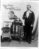
You can see the small motor in the very back of this photo
user posted image
this is the resister banks that were set to 240v and are now set at 110v
user posted image
wjw - February 22, 2009 06:00 AM (GMT)
I was inspired by the foregoing to check the plug to the motor on my Victrola with the universal motor. The reading is 120v! I expected 32-36. The motor runs fine with no visual arcing just as it has for me these past 30 years. Could my digital VM be reading "through" the resistor bank. With my vast expertise I can reliably say "I dunno". Moo, if you were I you would run the motor for ten minutes with the brush cover off, look for arcing at the brushes and feel the sides of the motor now and then for any heat. Dan, whatcha think about my volt meter reading of 120?
[Marjorie Main] - February 23, 2009 01:19 AM (GMT)
Very interesting!
The input voltage at the connections to the motor is 120v?
Hmmmmm- is the multi-tester set to read AC or DC? Given that it's a universal motor (AC or DC), it should have a field coil to regulate the speed, IIRC. Whats the voltage on the field coil (if you can find the field coil)?
Dan
Brad - February 23, 2009 03:08 AM (GMT)
Not having a schematic, and being a EE (but one that only pushes 1's and 0's around) I could hazard a guess: (warning - rambling explanation of Ohms law follows)
If the resistance is in series with the motor, voltage across the motor and the resistor is proportional to the the current time the resistance (for each one).
If the motor is off and you are trying the measure the voltage at the motor, you would see a voltage nearly equal to your source voltage because the resitance of the voltmeter is very very very high, which means very very very low current is flowing. Very very very low current through the resistor drops very very very little voltage, thus you would see the full voltage at the motor when it is off.
Try measuring the voltage drop across the resistor when the motor is off and is on.
I'm going back to being a couch potato now B)
orthophonic - February 23, 2009 04:10 AM (GMT)
The input voltage would be line voltage and if the motor is not in operation, the voltage would be the same at the motor across the switch when opened. When the motor is in operation, the resistor banks should "pull" the voltage down along with the motor so that ACROSS the motor leads themselves, the voltage would be at or near rated voltage when all is working fine. If a brush loses contact with the motor's commutator, the voltage would then go back up to line voltage as none would then be flowing through the motor/resistor circuitry. The motor is assumed to be a motor that has the field would either parallel to the armature windings or in series; it doesn't matter. The motor will rotate in the same direction regardless of the polarity of the input voltage unless either of the input leads of the armature or the field are reversed in direction. The only way a motor of this type will change direction with a change in the polarity of the input voltage is when the field is a permanent magnet and thereby has no electrical connections. That is why an electric drill or a vacuum cleaner will run in the same direction regardless of whether they are fed AC or DC of either polarity if you disregard other circuitry that may be connected to them such as electronic speed controls and such. BTW, the started motor in a car will turn the engine in the same direction no matter what way you connect the battery unless it has a permanent magnet field. If you do this, however, the diodes in the alternator will be VERY unhappy!!! Hope this helps! :woof: :woof: :woof:
electrofreak - February 23, 2009 04:52 AM (GMT)
Brad has the best take on this He (as I) is a grad EE. A universal motor is always a series motor. That is, that the field windings are always connected in series with the armature.
Through all of this, I was assuming that the voltage at the motor was being measured with the motor running. That's the way it has toi be in order to measure the conditions at the motor.
It appears that the thing is running properly as Moo has connected it. I might only suggest that if the resistor bank would be so designed, a connection for 130 Volts would be advisable, because of the use of higher line voltages today.
My Victor Electrola XVI has the first of the universal motors I've ever had. I am pretty sure that I'll make up a little DC power supply for it, as I described above. I just bdon't feel comfortable with all of that heat coming from the back of the cabinet.
wjw - February 23, 2009 04:58 AM (GMT)
Brad and Ortho, thanks so much for this. I was trying for a dropped reading without a completed circuit.
Moo, if you're out there, we have to read the voltage as it is fed to the motor while it's running.
wjw - February 23, 2009 05:52 AM (GMT)
Past my bedtime, but just measured voltage with the motor running. Digtal voltmeter is pretty jumpy reading this thing but it never bounced above 34 V. I'm happy now. Thanks again, guys.
Moooperator - February 24, 2009 03:38 PM (GMT)
I've been playing it on the "Victrola" mode and it is working fine as far as the motor is concerned. No heat and no arching. When it is in the change mode it will not stop changing records. The bracket that releases the changer is held over by an electric magnet I think but when it is finished it does not go back in place. I don't know if the spring that has pull tension on it is weak or the magnet does not shut off... I guess that is my next adventure.
Phonojim - February 24, 2009 05:47 PM (GMT)
To add to Orthophonic's explanation, a resistor will only drop voltage if there is current through it, and the voltage drop across the resistor will be prortional to that current. Therefore, if there is no load to draw current (as when the motor is off) there will be no voltage drop and the measured voltage at the motor plug will be line voltage.
By the way, courtesy of Florida Power and Light, our line voltage here has at times been as high as 132. At that point I began unplugging things and called them. They fixed it , but 127 is not uncommon here.
PJ
[Marjorie Main] - February 25, 2009 01:43 AM (GMT)
QUOTE (Moooperator @ Feb 24 2009, 10:38 AM)
I've been playing it on the "Victrola" mode and it is working fine as far as the motor is concerned. No heat and no arching. When it is in the change mode it will not stop changing records. The bracket that releases the changer is held over by an electric magnet I think but when it is finished it does not go back in place. I don't know if the spring that has pull tension on it is weak or the magnet does not shut off... I guess that is my next adventure.
Put a compass near the coil for the magnet and see if the polarity changes when the magnet is supposed to activate.