![[The Talking Machine Forum - For All Antique Phonographs & Recordings]](/styles/we_universal/theme/images/the_talking_machine_forum.png)

Hello,
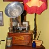
I have cleaned up my Class M and would like to restore it to running condition. Unfortunately the wiring seems to be incorrect and I am looking for assistance in getting it strait.
Is there anyone out there who has a working Class M and willing to photograph the underside for me or have a schematic which they can scan in?
Here is a photo of my machine and the underside motor and wiring.
Thanks
Bruce
Need Help - Wiring a Class M
-
Bruce
- Victor III
- Posts: 578
- Joined: Mon Jan 02, 2012 9:15 pm
- Location: Vancouver, Canada
Need Help - Wiring a Class M
- Attachments
-
-
-
Chuck
- Victor III
- Posts: 892
- Joined: Fri Mar 25, 2011 11:28 pm
- Personal Text: Richards Laboratories http://www.richardslaboratories.com producing high quality cylinder blanks
- Contact:
Re: Need Help - Wiring a Class M
Bruce,
Thanks so much for posting that picture of
the class M motor. The only other time I've
ever seen one of those motors was at Union
a few years ago. There was a class M in
"basket case" shape and I opened it and spent
a lot of time examining the motor!
I've never worked on one yet, but I do see
a few things there in your picture:
Near the bottom of the picture there is a
copper-colored casting held on to a post
that protrudes up from one of the field-magnets.
This casting looks to be adjustable as far as position, and on the other end it has what
looks to me to be a black curved insulator
piece perhaps made of bakelite. There are
two holes in this black insulator piece, and
those holes look to be where the brushes
mount. The brushes appear to be the two
brass things with wires on them near the bottom
of the picture.
I also see that this motor is a 4-pole
arrangement, that is, it has 4 field magnets.
Those magnets look to be wound electromagnets
too, not permanent magnets such as are found
today in many small motors.
The commutator looks to be on the top
surface, near the center. That makes sense
with the location of what looks like the brush
holder and the brushes to me.
A four-pole motor. Looks exactly like a
600 volt streetcar motor in miniature!!
My next wondering is whether it is meant
to have the field magnets in series with
the brushes. That would be my guess, as Edison
obviously wanted to get the most life out
of the grenet cell when running the machine.
DC motors which have wound fields can be
wired either series or parallel, but parallel
tends to use quite a bit more current than
series does.
Others will know more and be able to tell you
about this wiring. But I am very much interested in this thread!
By the way, if you would ever want to fire
up the grenet cell and actually run the
machine using it, I have the info about the
chemicals needed to do that, and how to go
about setting one of those cells up for service.
That is another interest of mine:
Early wet-cells. The grenet cell is a real
workhorse. Not a lot of hours per batch of
chemicals, but it has current to spare!
When not in use, the plates are drawn up out
of the solution and locked up with the thumb
screw on the center rod. That keeps it from
using itself up when it sits around for a while. It is a form of what was known
as a "plunge cell".
Looks like a great machine and with just a little TLC, it should run just fine!!
Chuck
"Sustained success depends on searching
for, and gaining, fundamental understanding"
-Bell System Credo
for, and gaining, fundamental understanding"
-Bell System Credo
-
edisonphonoworks

- Victor IV
- Posts: 1566
- Joined: Wed Oct 21, 2009 10:50 am
- Personal Text: A new blank with authentic formula and spiral core!
- Contact:
Re: Need Help - Wiring a Class M
I don't know if this is helpful.
- Attachments
-
- 00499879.pdf
- Perfected Patent.
- (1.12 MiB) Downloaded 198 times
-
Bruce
- Victor III
- Posts: 578
- Joined: Mon Jan 02, 2012 9:15 pm
- Location: Vancouver, Canada
Re: Need Help - Wiring a Class M
Thank you both for your information. I have discussed your suggestions with an electrician neighbour of mine and he is interested in taking a look in the near future.
I will post the results.
Bruce
I will post the results.
Bruce
-
Chuck
- Victor III
- Posts: 892
- Joined: Fri Mar 25, 2011 11:28 pm
- Personal Text: Richards Laboratories http://www.richardslaboratories.com producing high quality cylinder blanks
- Contact:
Re: Need Help - Wiring a Class M
Bruce and Shawn,
Just had a look at the PDF file you posted, Shawn.
Everything is clearly shown and described there.
This motor turns out to have been wired with the field magnets being
in parallel with the armature and brushes. The reasons Edison did it that way
are all clearly explained in the text.
10 and 6 apparently is the "plug switch" which turns the machine on and off.
N and N' are the motor brushes.
Main terminals are 3 and 4. 3 connects to wire 1 and 4 connects to wire 2.
Very ingenious and interesting the way Edison decided to use a sensitive relay
to switch the armature in and out, depending upon the governor.
Meanwhile, the field magnets themselves are all in series, but as a whole, they
are right across the main battery, being only controlled by the plug switch.
Bruce, with a copy of this PDF that Shawn posted, you will have no problem
wiring this machine. Please contact me off list to discuss this if there is
anything about the diagram or text that you might need some help understanding.
I would think that with an ohm meter, a volt meter, some clip leads, and a DC power supply of about
2 volts that can supply a few amps of current, that this motor can be all set up
and made to run well. First step is to ohm out the field coils to make sure they are
conducting properly and not open. Then maybe same for the relay coil. Then look for any sign
of loose or broken wires on the armature, but it's probably fine. Then put the brushes on
the holder, clip it up, and do some experiments.
My email is [email protected]
Chuck
"Sustained success depends on searching
for, and gaining, fundamental understanding"
-Bell System Credo
for, and gaining, fundamental understanding"
-Bell System Credo
-
Bruce
- Victor III
- Posts: 578
- Joined: Mon Jan 02, 2012 9:15 pm
- Location: Vancouver, Canada
Need Help - Wiring a Class M - THANK YOU
Hello,
I would like to than those who provided advice and assistance, specifically;
Chuck "Richards Laboratories"
Dwayne Wyatt
Domenic DiBernardo
and
Shawn Borri "Edsonphonoworks"
My machine now works, hooked up to a variable speed toy train transformer, and will be complete once I find the correct Edison Carriage arm and Automatic Reproducer.
Thank You!
Bruce
- Attachments
-
-
fran604g
- Victor VI
- Posts: 3997
- Joined: Mon Mar 04, 2013 2:22 pm
- Personal Text: I'm Feeling Cranky
- Location: Hemlock, NY
Re: Need Help - Wiring a Class M
Bruce, thank you for creating this post, I found it very interesting to be able to see a working model and the resources that were posted by the additional members!
Nice "M"!
Best,
Fran
Nice "M"!
Best,
Fran
Francis; "i" for him, "e" for her
"Even a blind squirrel finds a nut once in a while" - the unappreciative supervisor.
"Even a blind squirrel finds a nut once in a while" - the unappreciative supervisor.